-40%
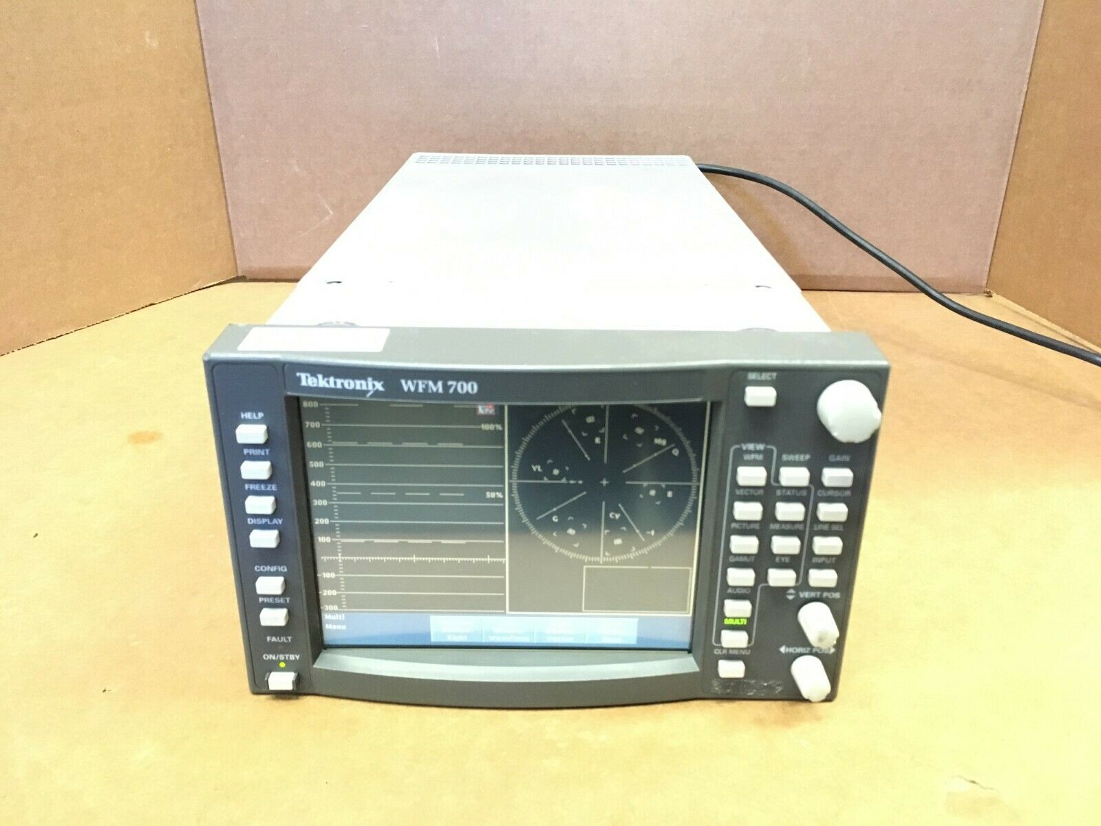
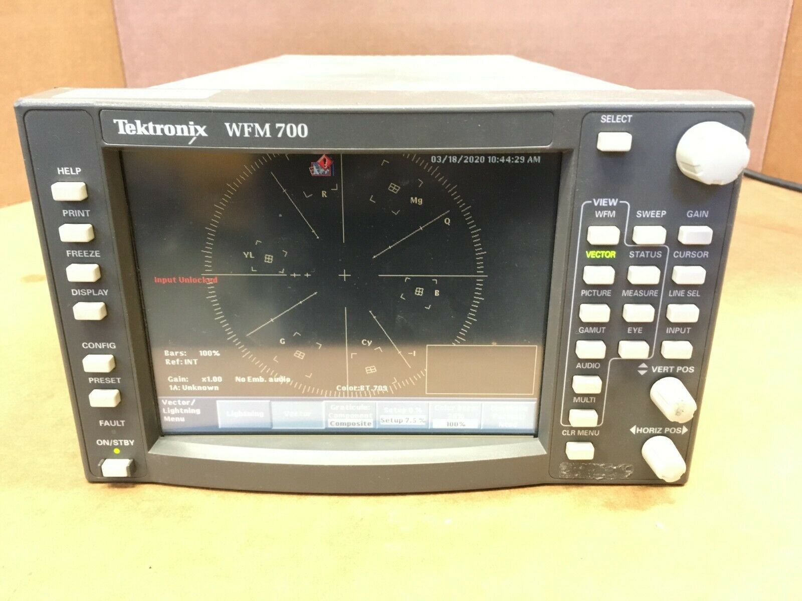
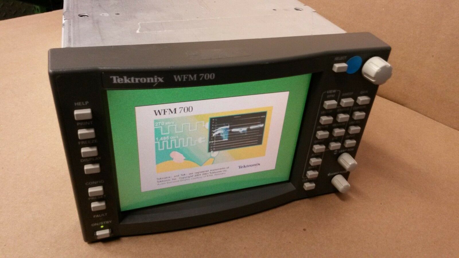
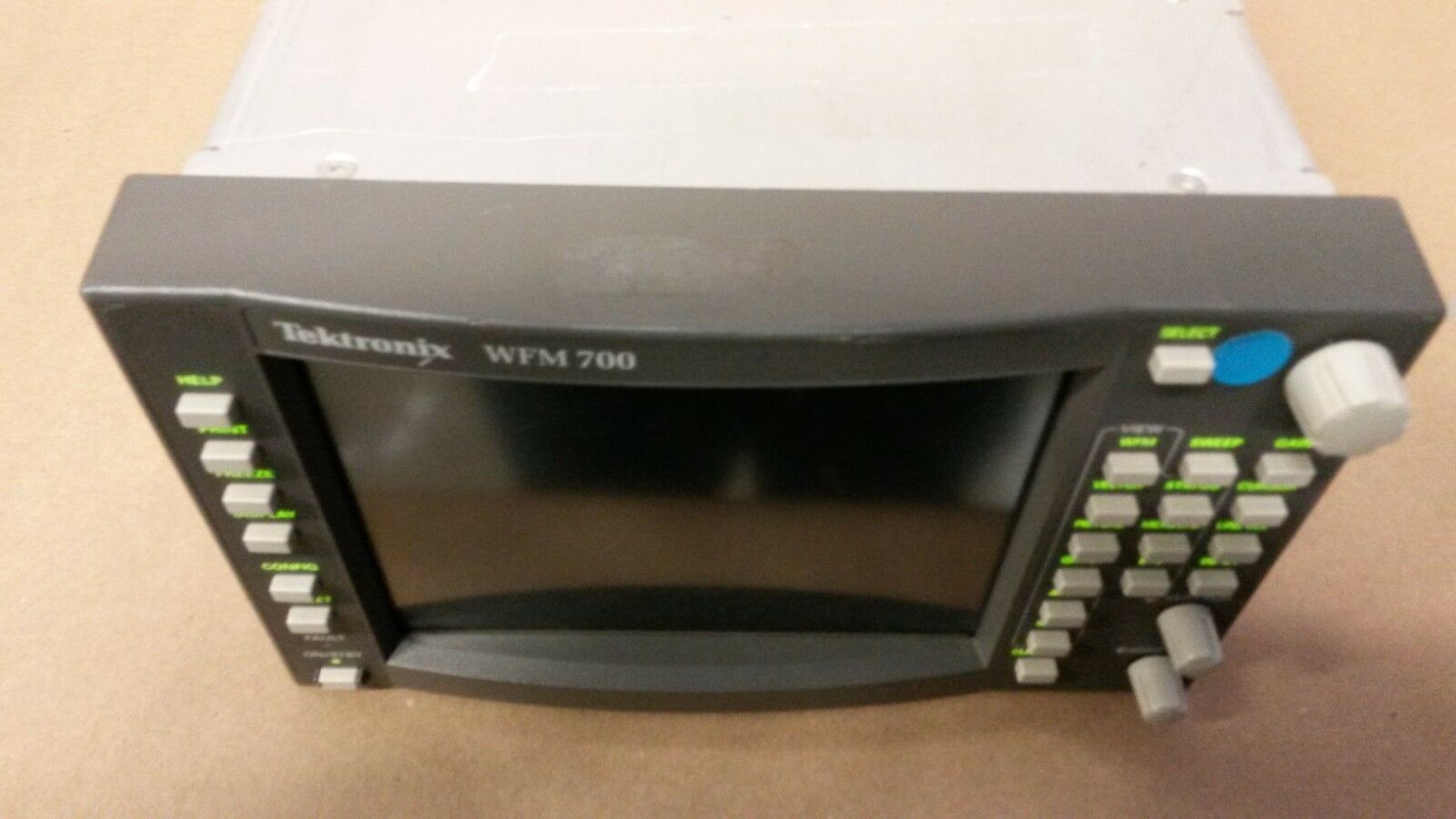
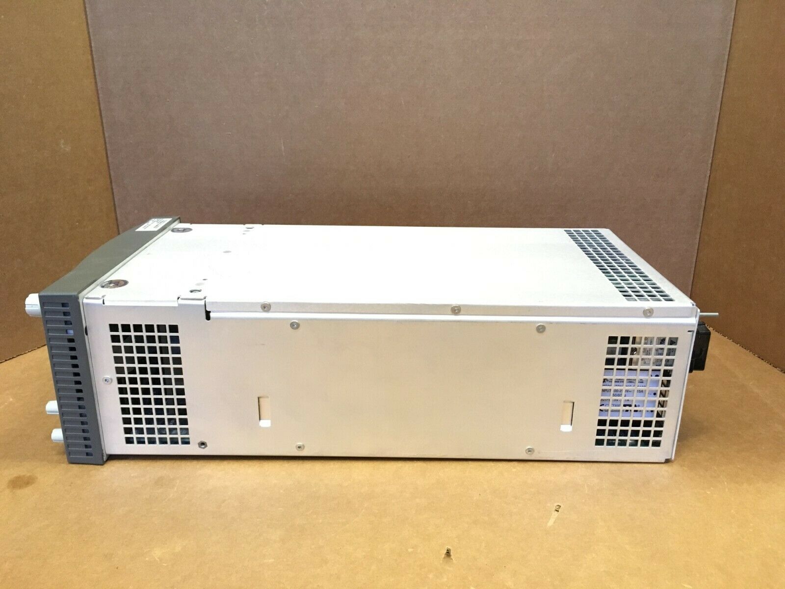
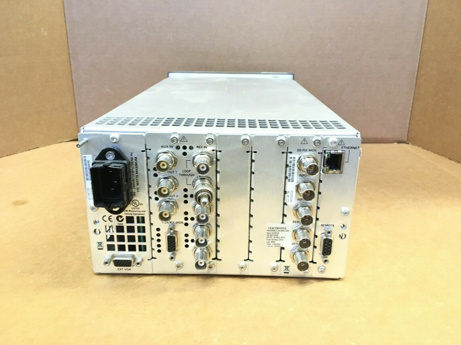
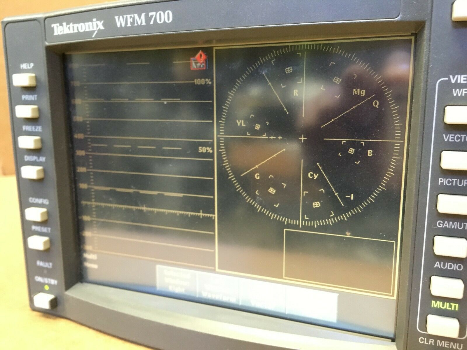
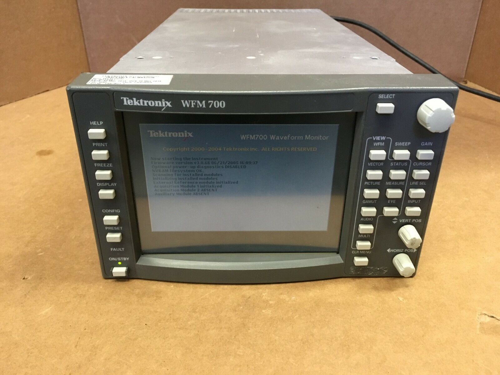
Tektronix WFM700 Multi-format Multi-standard Waveform Monitor
$ 343.19
- Description
- Size Guide
Description
Sellercore: HTML PreviewPCXUSA
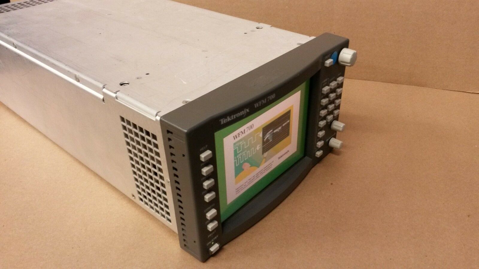
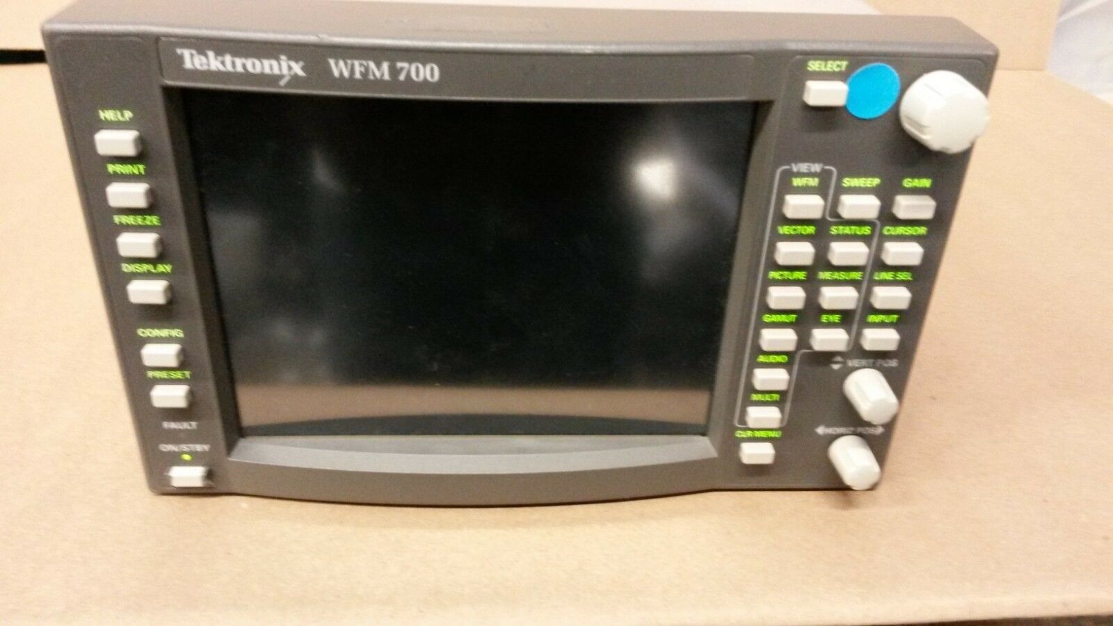
Tektronix WFM700
Multi-format Multi-standard Waveform Monitor
Features & Benefits
Monitors SD and HD digital component video - single product for both standards
Exclusive Diamond, Split Diamond and Arrowhead displays offer unique insight into the gamut compliance of your content
Safe Action and Safe Title Graticules help editors and operators easily identify incorrectly positioned video content
Multi-mode display improves efficiency by letting you view a wide variety of displays simultaneously
Fully digital processing for accuracy, repeatability, stability and reduced cost of ownership
Closed Caption detection and decode let operators quickly verify correct closed captioning in the video content
Ancillary data analysis reduces the time and effort needed to isolate and diagnose problems in the data content of video signals
Comprehensive error detection, reporting, and logging offer powerful support for content QA and service-level verification
Configurable alarms with user-adjustable thresholds let you select a level of monitoring most suited to your application
HD/SD Eye Pattern Display with automated measurements and Jitter Display improve efficiency in the installation and maintenance of digital video distribution system (M module only)
Digital audio monitoring capability with surround sound verifies compliance of digital video and digital audio signals in a single instrument, conserving space and lowering capital expenses (requires purchase of additional module).
TFT Color LCD Display, with integrated touch screen control, provides a unique, flexible user interface with intuitive, status-at-a-glance operation
Remote interface for access and control from any location
Applications
Quality control in the production and post-production of HD/SD digital video content
Monitoring and compliance checking in the distribution and broadcast of HD/SD digital video
Video equipment qualification and troubleshooting in the installation and maintenance of HD/SD digital video facilities and systems
The WFM700 Series of Multi-format Waveform Monitors offers the monitoring capabilities needed in the production, post-production, distribution, and transmission of high-definition (HD) and standard-definition (SD) digital video content.
For mixed HD/SD environments, the multi-format
WFM700A
gives you the tools you need to perform operational monitoring tasks like checking signal validity and content quality, setting levels, and verifying signal paths. The
WFM700HD
offers an HD-only version of these same capabilities. The
WFM700M
offers all the capabilities of the WFM700A plus the digital analysis capabilities important in the design, installation, and maintenance of digital video systems, including eye diagram with automated measurements, jitter, and data measurements for both HD and SD formats. With available digital audio monitoring support, you can expand the capabilities of any WFM700 configuration to monitor both digital video and audio in a single instrument.
These products combine the best of traditional waveform monitors with the measurement accuracy, repeatability, and stability achievable with fully digital technology. Their modular design lets you purchase the capability you need now and add capabilities later as your requirements change. Backed by Tektronix innovation, service, and support, these modular, multi-format, fully digital waveform monitors lower your cost of ownership while offering powerful tools for monitoring digital video and audio signals.
Tektronix-exclusive Color Gamut Monitoring
Problems with production and operational equipment can introduce illegal colors in the digital video signal, i.e. colors that fall outside established gamut limits. Every member of the WFM700 Series has the following Tektronix patented gamut monitoring displays:
Diamond and Split Diamond – monitoring for RGB gamut compliance
Arrowhead – monitoring for composite gamut compliance including luma+chroma and separate luma limit checking
With these specialized displays you can significantly reduce the time and effort needed to perform this critical quality control task:
The Diamond Display helps you quickly and easily analyze RGB gamut problems. At a glance, you can tell if any part of the signal trace lies outside the graticule, indicating a gamut error. The display's construction makes it easy to isolate the source of the problem. Errors appearing only in the upper diamond indicate a problem with the blue component, while errors appearing only in the lower diamond indicate a red component problem. An error that appears in both diamonds exposes a problem with the green component. The Diamond display gives you a unique, visual indication of signal components that are causing gamut errors so you can quickly make the adjustments needed to correct the problem.
WFM700 Diamond display
The Split Diamond display separates the two diamonds to help you easily detect component values below the black level. Both the Diamond display and the Split Diamond display offer user-adjustable thresholds for the white and black level of each component, and a single touch returns you to default settings quickly.
WFM700 Split Diamond display
Often, digital video in component format is converted into NTSC or PAL composite video format for transmission. Due to differences in component and composite color spaces, video signals that fall within legal RGB color space may not convert into signals that fall within a legal composite gamut.
The Arrowhead display helps you quickly detect this type of color gamut error, without the need for a separate composite encoder. To form the Arrowhead display, the WFM700 transforms the component signal into an NTSC or PAL composite signal representation and plots the luminance component of this signal vertically against the chrominance component plotted horizontally. Component signal values that correspond to out-of-gamut NTSC or PAL composite signal values will lie outside the legal region shown on the Arrowhead display.
You can adjust the thresholds used to define out-of-gamut conditions in the Arrowhead display, tailoring the monitor's operation to fit your specific requirements. The Arrowhead display has adjustable luma+chroma limits and luma-only limits. Each allows user-defined upper and lower limits. You can easily assess luma-only and luma+chroma compliance all within the Arrowhead display.
WFM700 Arrowhead display
Familiar Waveform Monitoring Displays and Controls
All WFM700 models offer familiar waveform displays. You can view digital video signal components in either an RGB, YRGB, YP
b
P
r
color space, displayed in parade or overlay mode. The YRGB color space combines the Y luminance signal with the RGB component signals to give you benefits from both traditional color spaces.
WFM700 YRGB Waveform display in parade mode
In addition to these digital waveform displays, the WFM700 products can also display a familiar composite representation of an SDI digital signal.
WFM700 Composite Waveform display
Every WFM700 model offers a rich set of familiar waveform display controls including:
1-line, 2-line, 1-field, and 2-field sweep selections
Line and field selects
Flat and low-pass filtering
1x, 5x, 10x and variable gain settings
0% and 7.5% setup levels in the composite waveform representation
Offset and aligned chroma settings in YP
b
P
r
color space
Horizontal magnification
Selectable graticules including mV, IRE, and % scales
When used in 2-line sweep mode, the magnify feature will automatically configure the instrument for optimal viewing of the horizontal blanking interval on any SD or HD digital signal, eliminating the need for tedious, trial-and-error adjustment.
Tradition and Innovation in Monitoring Color Amplitude and Timing
Complementing these full-featured waveform displays, every WFM700 product offers two specialized displays for monitoring the color information in digital video signals.
The traditional Vector display for monitoring P
b
P
r
color amplitude
The Tektronix-patented Lightning display for monitoring luma and chroma amplitudes and interchannel timing
The Vector Display gives you a choice of representations, either component graticule or composite graticule. The composite representation is independent of the input signal colorimetry and gives the best indication of hue shift. The component representation allows comparisons with equipment having similar Vector display representations.
Selecting the composite graticule will show the color vector with the traditional compass rose display. You can manually configure the compass rose for the appropriate composite standard, either NTSC or PAL, or let the instrument automatically select the appropriate display based on the type of signal monitored. Like the composite analog waveform representation, you can apply either 0% or 7.5% setup levels to waveforms.
In the component representation, you can configure the display to either show or remove the compass rose graticule. You can also choose to display the I and Q color axes.
WFM700 Vector display with composite graticule (compass rose)
The Tektronix-exclusive Lightning Display combines chrominance and luminance information in a unique approach that helps you quickly detect and isolate amplitude and timing problems in these signal components. Most importantly, you can use a standard color bars signal to make these measurements. You do not need to use special test signals. Only the Lightning display gives you the ability to use readily available signals for making these critical measurements, saving you both time and resources.
The Lightning display is especially useful in detecting and isolating interchannel timing problems. Bowing of traces in the upper half of the display represents a timing problem between Y and P
b
, while bowing in the lower half of the display represents timing errors between Y and P
r
. Calibrated graticule marks on the display help you quantify these timing errors.
WFM700 Lightning display
You can set either 75% or 100% color bar targets on both the Vector and Lightning display, or use the gain settings to normalize signal amplitudes. In the Lightning display you can use the magnification settings to expand the display scale for better viewing of the graticule marks.
Automatic Detection of a Wide Range of Signal Formats
All WFM700 models have two terminating inputs for serial digital signals in either SMPTE 292M format (WFM700 HD, WFM700A, and WFM700M) or SMPTE 259M format (WFM700A and WFM700M). The following table shows the supported signal formats
Characteristics
Serial Digital Video Interface
Video Inputs -
2 per card - only one active at a time.
Input Type -
75 Ω BNC, internally terminated.
Launch Amplitude Accommodation -
800 mV ±10% for full specification.
800 mV ±30% up to 20 dB cable attenuation.
Jitter Tolerance -
0.4 UI
p-p
typical above 2 MHz.
Return Loss -
15 dB to 1.5 GHz.
Isolation Between Inputs -
>45 dB to 1 GHz.
Switched Serial Video Output
Format -
1.485 Gbps or 270 Mbps repeat of selected input.
Output Level -
800 mV
p-p
±5% into 75 Ω load.
Return Loss -
15 dB to 1.5 GHz.
Output Type -
75 Ω BNC.
External Reference
Sync Format -
NTSC, PAL, 1080i 50 Hz, 1080i 59.94 Hz, 1080i 60 Hz, 720p 59.94 Hz, 1080p 23.98 Hz, 1080p 24 Hz.
Input Type -
75 Ω BNC passive loop.
Return Loss -
40 dB to 30 MHz.
Hum -
Operates with 500 mV
p-p
.
Signal/Noise -
Operates to 25 dB.
Serial SD Only Monitor Output
Content - Follows Active Input With Brightups -
SD only digital version of RGB/Y′P′bP′r analog pix monitor output on Ref board.
Rate -
270 Mbps.
Signal Level -
800 mV ±5% into 75 Ω.
Return Loss -
20 dB, 5 MHz to 270 MHz.
Output Type -
75 Ω BNC.
Picture Monitor Outputs
Signal Format, BNC Outputs -
Y, P′b, P′r with sync on Y, RGB with sync on all, HD and SD. HD sync is tri-level.
Signal Format, VGA DSUB Outputs -
Same signal as on BNC outputs, also have TTL H and V drive.
Impedance -
75 Ω unbalanced.
Active Video Accuracy -
700 mV ±5%
p-p
(Y′P′bP′r mode).
Black (Blanking) Output Level -
0 mV ±25 mV for HD and SD.
Frequency Response, SD -
Y, G, B and R ±5% to 5.5 MHz.
Frequency Response, HD -
Y, G, B and R ±8% to 30 MHz.
AES Audio Interface
Audio Inputs -
4 inputs, 8 audio channels, meets Requirements of AES-3id-2001.
Input Type -
75 Ω BNC, internally terminated, unbalanced.
Input Amplitude Range -
0.2V to 2V peak-to-peak
Input Sample Rate -
32k to 96k samples/sec
Input Lock Range -
> ±5%, typical
Input Return Loss -
Better than 25dB from 0.1 to 6 MHz.
Audio Outputs -
Up to 8 audio channels from Embedded Audio only
Output Format -
48 kHz, 20 bit, meets requirements of SMPTE 276M-1995 (AES-3id-2001)
Output Amplitude Range -
0.9V to 1.1V peak-to-peak into 75 Ω
Output Sample Rate -
Locked to embedded sample rate (nominally 48 kHz)
Output Jitter -
Meets AES3-1997
Output Return Loss -
Better than 25 dB 0.1 to 6 MHz
Waveform Vertical Deflection
Vertical Measurement Accuracy Using Graticule or Cursor -
At 1x, ±0.5% of 700 mV full scale.
At 5x, ±0.2% of 700 mV full scale.
At 10x, ±0.1% of 700 mV full scale.
Gain -
1x, 5x, 10x, variable.
Variable Gain Range -
0.25x to 14x.
Frequency Response, HD*
1
-
Luminance channel (Y): 50 kHz to 30 MHz ±0.5%.
Chrominance channels (P′b, P′r): 50 kHz to 15 MHz ±0.5%.
*
1
For monochrome signals, R, G and B bandwidths equal Y bandwidth.
Waveform Horizontal Deflection
Sweep Accuracy -
±0.5%, all rates, fully digital system.
Sweep Linearity -
0.2% of time displayed on screen, fully digital system.
Rates -
1, 2, 3, 4 line or field, depending on mode.
Line Select -
Selected line in 1 line, selected first line in 2 line or parade.
Eye Pattern Display
Type -
Equivalent time sampler.
Signal Bandwidth -
50 kHz to 2.5 GHz at -3 dB point.
Timebase Jitter -
(Note: in 1 kHz high pass filter)
(HD) - 70 ps, typical.
(SD) - 150 ps, typical.
Eye Clock Bandwidth Accuracy -
Actual -3 dB point within 10% of nominal.
Display Modes, SD -
Overlay: Overlays all bits to form each eye opening. Useful for observing peak jitter.
10 Eye: Displays eye relative to the parallel clock and line sync. Useful for observing jitter correlated to line rate and word clock.
Display Modes, HD -
Overlay: Overlays all bits to form each eye opening. Useful for observing peak jitter.
20 Eye: Displays eye relative to the parallel clock and line sync. Useful for observing jitter correlated to line rate and word clock.
Jitter Display
Type -
Demodulated recovered clock per SMPTE RP184.
Digital Readout -
Accuracy: <0.05 UI + 10%, typical, of reading for jitter frequencies from three times high-pass filter selection to 1 MHz.
Note:
High-pass filter selection is set in Jitter Waveform Mode.
Jitter Waveform Gain Error -
<0.1 UI + 10%, typical, of reading for jitter frequencies from three times high-pass filter selection to 1 MHz.
Jitter Waveform High-pass Filter Selection -
10Hz, 1kHz, 10kHz, 100kHz
Jitter Output -
100 mV/UI, ±10% into 75 Ω load.
Jitter Frequency Response -
-3dB at 5 MHz (typical)
RGB Gamut Error Detection
Detection Level -
High Limit, +630 mV to +756 mV in 1 mV steps.
Low Limit, -50 mV to +35 mV in 1 mV steps.
Arrowhead (NTSC/PAL Composite Gamut Limit Display Mode)
Detection Level -
Accuracy, ±7 mV.
Luma+Chroma High Limit (NTSC-derived formats), 90 IRE to 135 IRE in 1 IRE steps.
Luma+Chroma Low Limit (NTSC-derived formats), -50 IRE to -10 IRE in 1 IRE steps.
Luma+Chroma High Limit (PAL-derived formats), 630 mV to 950 mV in 1 mV steps.
Luma+Chroma Low Limit (PAL-derived formats), -400 mV to -100 mV in 1 mV steps.
Luma only High Limit, 90% to 108% in 1% steps.
Luma only Low Limit, -6% to +5% in 1% steps.
Audio Level Meter
Level Meter Resolution -
0.05 dB steps @ 10dB scale, from full scale to –40dB FS
0.25 dB Steps @ 0 to –70 dB scale, for signals above –40dB FS.
Level Meter Accuracy -
0.2 dB from 20 Hz to 20 KHz with 0 to –40 dBFS sine-wave input. PPM Ballistic mode except within 7 Hz of some submultiples of the 192 KHz oversampling frequency. For example:
13.714 kHz ± 7 Hz – 0.22 dB
16.0 kHz ± 7 Hz – 0.30 dB
19.2 kHz ± 7 Hz – 0.43 dB (worst case)
General Specifications
Power
Mains Voltage Range -
100 to 240 VAC ±10%.
Mains Frequency -
50 or 60 Hz.
Power Consumption (typical) -
≤100 W with 1 Video Input Module.
≤125 W with 2 Video Input Modules.
150 W max.
VGA O/P -
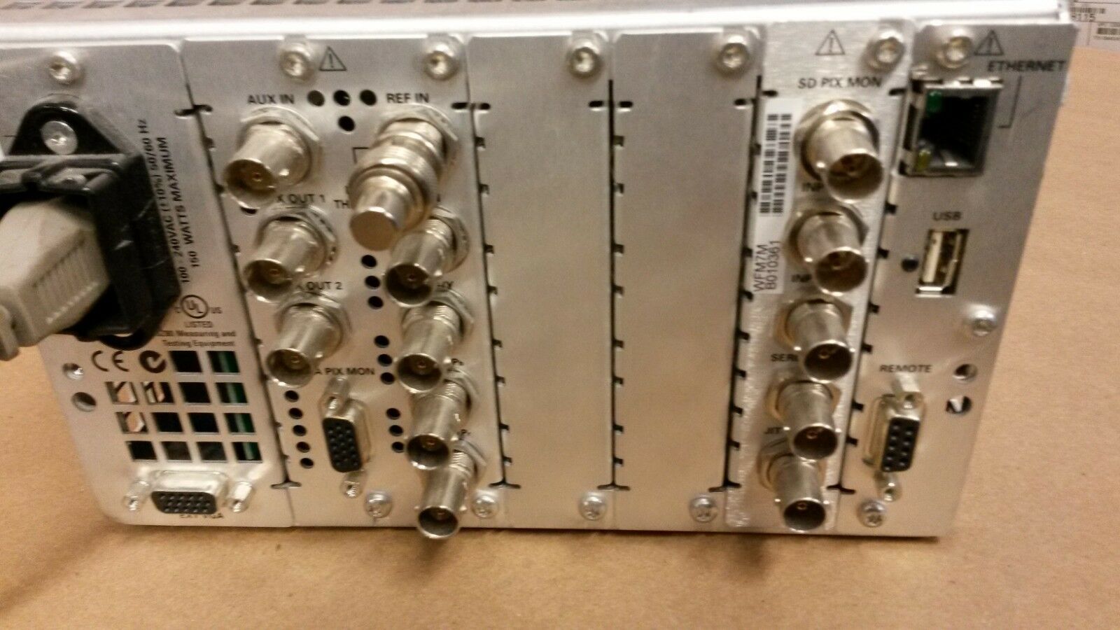
This connector allows the front panel display to be replicated on a remote VGA monitor.
Ethernet Connector -
Allows the instrument to be connected to a 10/100Base-T Ethernet circuit for remote control and firmware update.
Environmental
Temperature -
0 °C to +40 °C (operating).
–20 °C to +60 °C (nonoperating).
Humidity -
20% to 80% RH at up to 40 °C, noncondensing (operating).
Altitude -
to 3,000 m (operating).
to 12,192 m (nonoperating).
Safety
Designed and tested for compliance with: ANSI/ISA s82.02.01, Can/CSA C22.2 No. 1010.1, IEC 61010-1, UL 3111-1, 93/68/EEC, and EN 61010-1
EMI
Tested for compliance with:
FCC, CFR Title 47, part 15, Subpart B, Class A.
EN 55103-1/2, Class B emissions.
European EMC directive, video standard.
Physical Characteristics
*W01-L*
Shipping Information Title
We will ship it
professionally with good method and extra material.
Condition: seller refurbished, tested
, 30 days warranty
.
LOCAL PICKUP IS ALWAYS AVAILABLE Hackensack, New Jeresy off Route 80 Exit 66
Terms of Sale
Return policy
After receiving the item, contact seller within
Refund will be given as
Return shipping
30 days
Money back
Buyer pays for return shipping
Refer to
eBay Return policy
for more details. You are covered by the
eBay Money Back Guarantee
if you receive an item that is not as described in the listing.
Payment details
Payment method
